Sajten stöder inte din webbläsare. Uppdatera webbläsaren eller ladda ner en annan
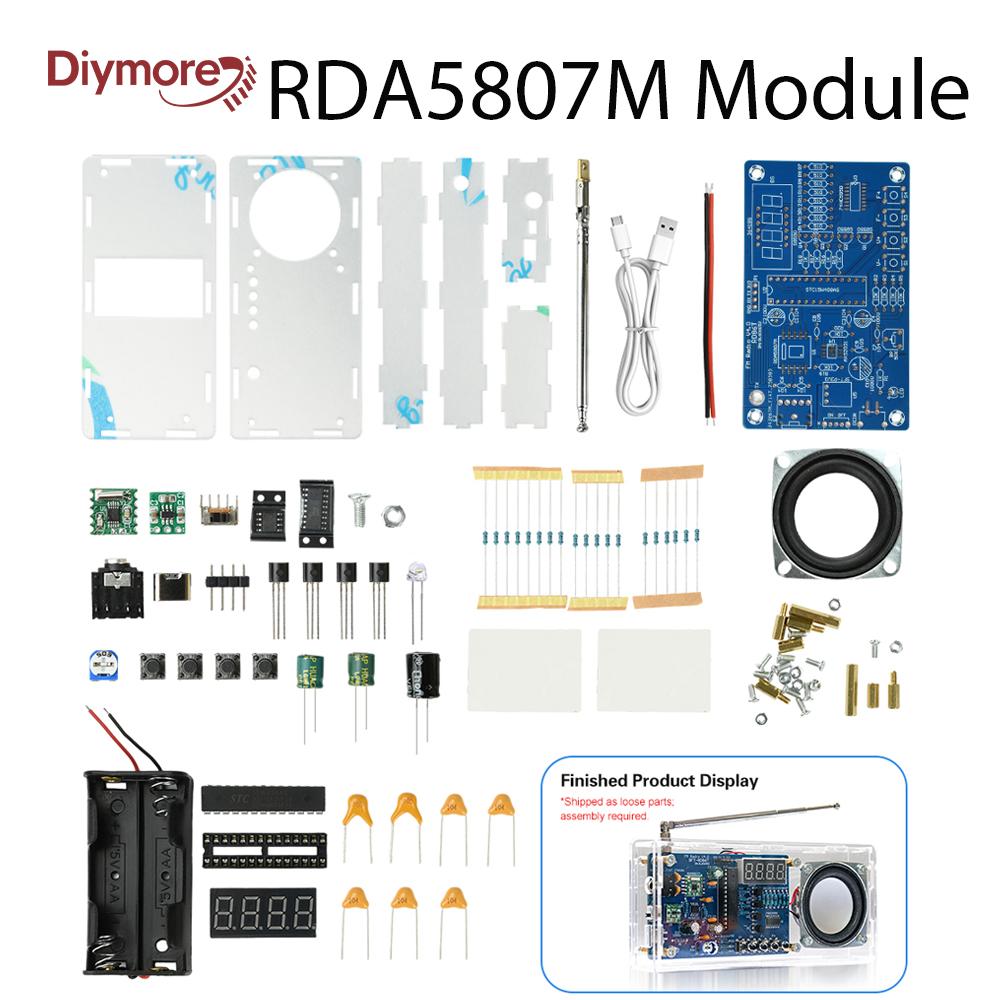
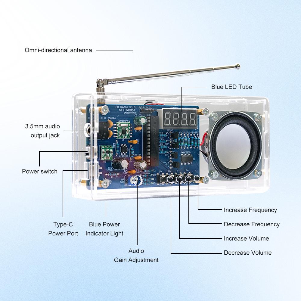
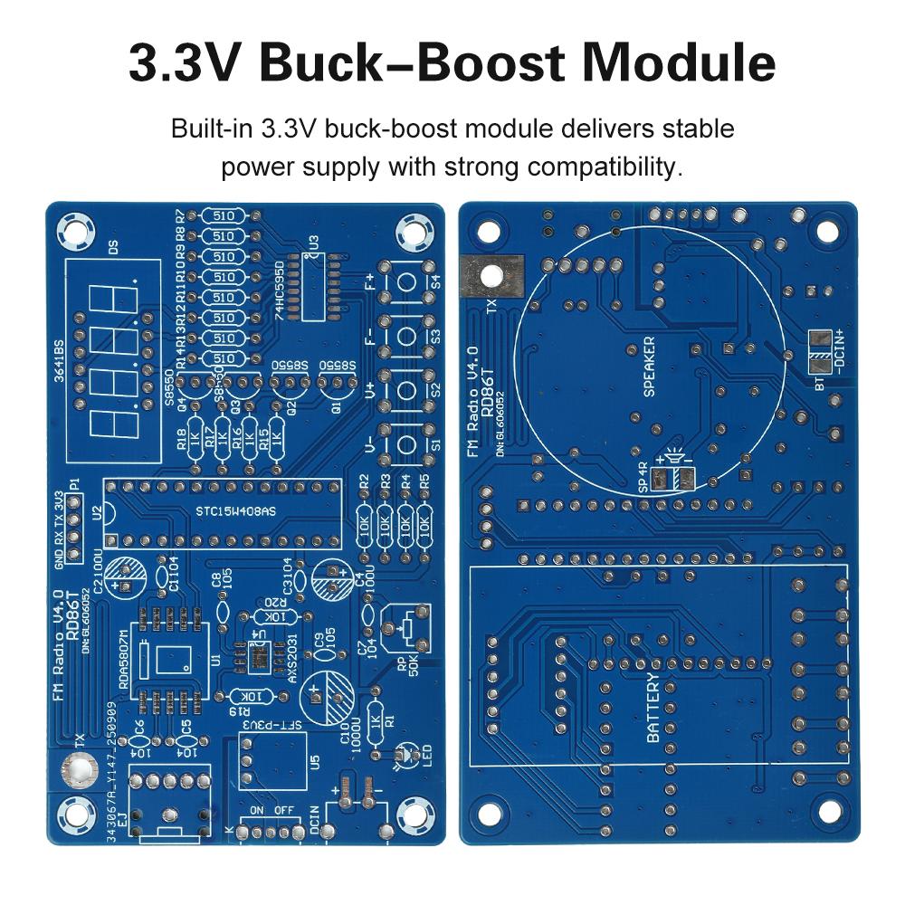
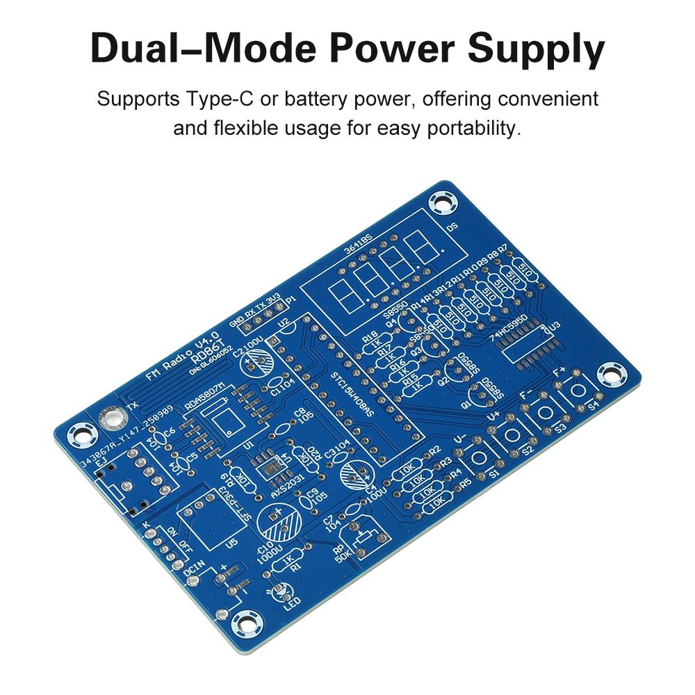
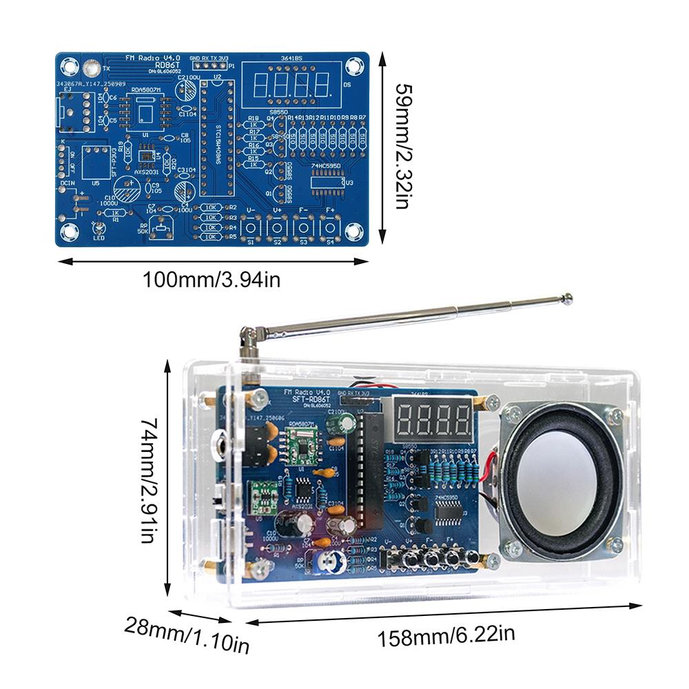


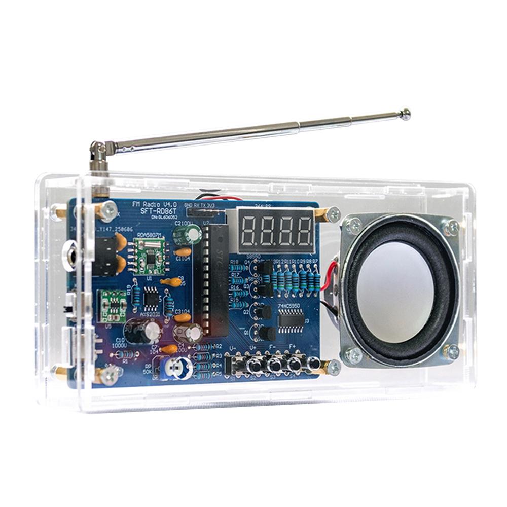
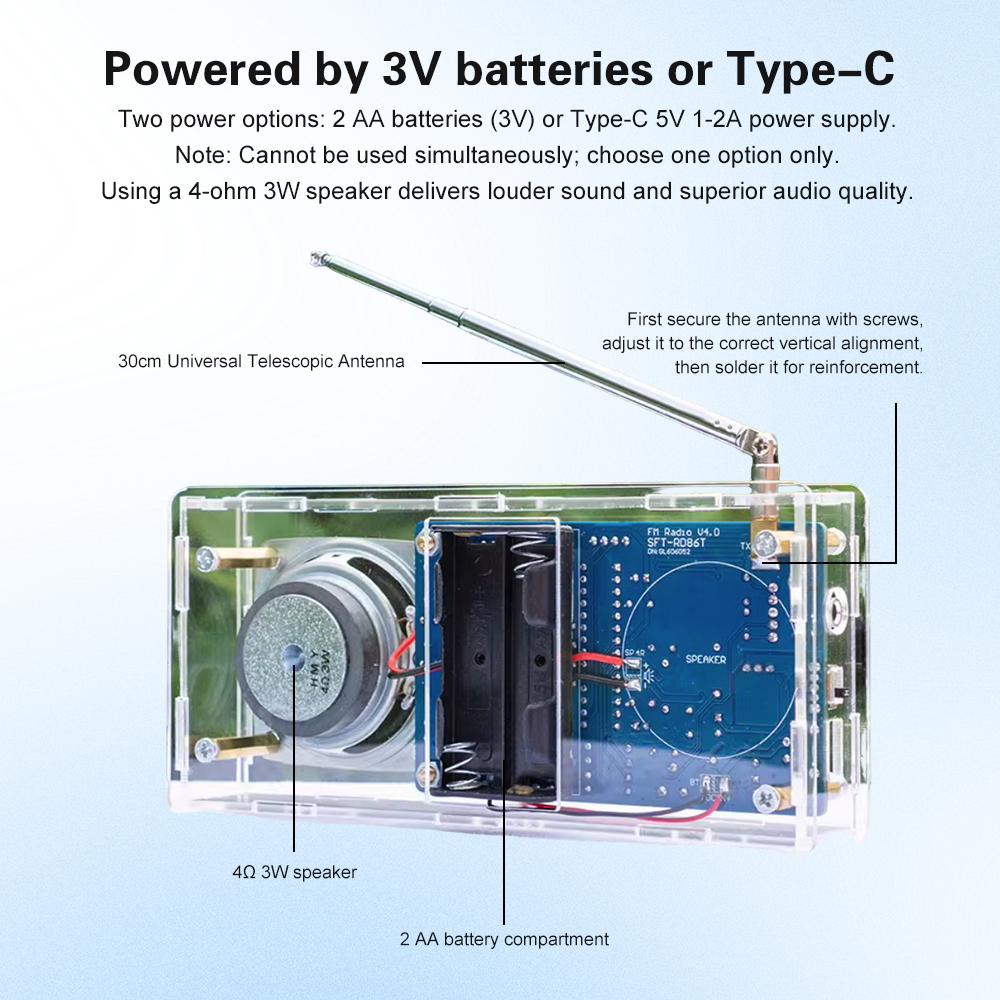
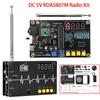
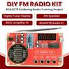
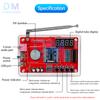
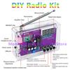
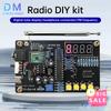
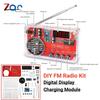
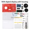
DIY FM Radio Electronic Kit Adjustable Frequency 87.5-108MHz Digital Display DIY Soldering Project Practice Solder RDA5807M
Nuvarande pris
Från Pris 332,70 krLaddar...
Laddar...
Laddar...
Laddar...
Laddar...
Laddar...
Laddar...
Laddar...
Laddar...
Laddar...
Laddar...
Laddar...
Laddar...
Laddar...
Laddar...

Fri frakt till USA
den 22 oktober

Dina betalningar och din integritet är säkra


 Återbetalning vid utebliven leveransKvalitetsgarantiSäker logistikIntegritetsskydd
Beskrivning


Vanliga frågor
- Vilka betalningsmetoder är tillgängliga på Joom?Joom stödjer ett brett spektrum av nationella och internationella betalsätt för europeiska kunder, inklusive betalkort och kreditkort (Visa, Mastercard, Maestro), PayPal, Apple Pay och Google Pay, samt landspecifika alternativ som Klarna, BLIK, Multibanco, MB WAY, SEPA och Giropay. Tillgängliga alternativ visas vid kassan och varierar beroende på land.
- Kan jag betala för ett dyrt köp i omgångar eller senare?Ja, tjänster för köp nu, betala senare, som Klarna och Scalapay, finns tillgängliga för vissa högre värde köp, beroende på ditt land, orderbelopp och leverantörens villkor.
- Kan jag spåra min beställning?Ja. Du kan följa leveransstatusen i Joom-appen eller på webbplatsen, uppdaterad allt eftersom paketet rör sig.
- Vad händer om min beställning inte anländer?Om din beställning inte anländer före leveransgarantidatumet, kontakta Joom-support så utfärdar vi en 100 % återbetalning. Vänligen låt oss veta om din beställning inte anländer innan det beräknade datumet så hjälper vi gärna till med en återbetalning.
- Är det säkert att betala på Joom?Ja. Joom använder ett säkert betalningssystem, och säljaren får inte betalt förrän du har mottagit din beställning, vilket ger ett extra lager av köparskydd.
- Vad händer om min beställning inte anländer eller produkten inte är som förväntat?Om din beställning inte levererades, anlände skadad eller inte stämmer överens med beskrivningen, kontakta Joom support — en full återbetalning kan utfärdas i dessa fall.
- Hur begär jag återbetalning?Öppna den relevanta beställningssidan och kontakta Supportchatt, tillgänglig på webbplatsen och i Joom-appen. Beskriv problemet och följ supportinstruktionerna.
Specifikationer
Tillstånd
ny
Tillverkningsland
Kina
Liknande produkter